Summary
The original strengthening scheme for the subject building was significantly revised as a result of peer review inputs to achieve a much safer building and ultimately save human lives during a major earthquake.
Background
The client is a leading Property Group with a portfolio of high-profile commercial buildings across New Zealand. The client purchased a four-storey commercial building in a high seismic zone. Then Engineer A was engaged to complete a Detailed Seismic Assessment (DSA) of the subject building and design a seismic strengthening scheme accordingly to achieve 100%NBS. Engineer A completed the required assessment and design work, which was then peer reviewed by Engineer B as required by the client and council for a Building Consent application.
Building Description
The building is a four-storey RC frame and shear wall building, designed and constructed in the 1950s. It is rectangular in plan. The structural layout is relatively regular in both plan and elevation, with the exception that there are shear walls located at the rear of the building. The primary lateral force resisting system includes moment resisting frames and shear walls in both transverse and longitudinal directions of the building. Figure 1 shows a typical layout of the structure including beams, columns and shear walls.
Figure 1 – Typical structural layout of subject building
What did Engineer A do?
Firstly, Engineer A performed a pushover analysis on the building as part of the DSA and seismic retrofit design. However, in this case the pushover could not be used due to its limitation in accordance with the relevant standards and guidelines. As a pushover is a static method of analysis, it cannot capture higher-mode effect. Therefore, when a building is sensitive to higher-mode effect, dynamic methods of analysis should be used. In this case, the higher-mode effect was assessed by comparing the storey forces of the first mode-only with that of the first and higher modes from linear dynamic analysis based on the Modal Response Spectrum Method (MRSM). It was found that the building was prone to the torsional and other higher modes of response. This meant that the pushover analysis would give inaccurate results.
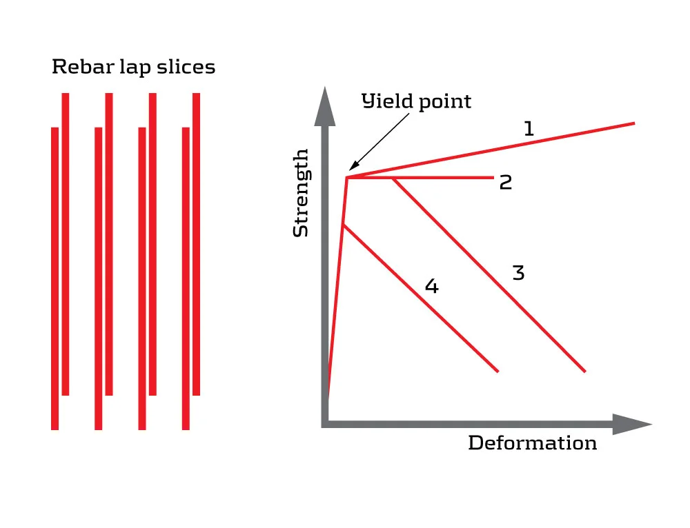
Secondly, the column inelastic behaviour was defined by Engineer A using Relationship 1 shown in Figure 2. This represents a generalized normal inelastic behaviour with the strength (force) increasing with the deformation beyond the yield point. However, when steel rebar lap splices are located within plastic hinge regions above each floor level, the strength may decrease suddenly before or after the yield point (Relationships 3 and 4) as shown in Figure 2. This behaviour depends upon several other factors, including:
Provided length of lap splices
Levels of axial loads
Anchorage or termination details of spliced rebars
Type of rebars - i.e., plain round or deformed rebars
Confinement provided by transverse reinforcement such as stirrups in the columns
Thirdly, Engineer A missed out important overstrength checks in the DSA and design. As mentioned before, plastic hinges limit forces to structural members by dissipating energy. What if the plastic hinges do not form at the expected locations and level of loading? Then, the demands are not limited and will continue to increase and eventually lead to undesired brittle failures prior to the formation of plastic hinges in the ductile members. As a result, brittle failures such as shear cracks of a beam or column, and a collector failure in a floor slab need to be assessed and suppressed at higher demands derived based on the overstrength of ductile members. In this case, the overstrength contributions included the following:
Statistical variation in the yield stress – i.e., some rebars have a higher yield stress than others.
Side rebars of floor beams – i.e., the side rebars were neglected in analysis, but contribute to flexural strength.
Slab flanges of floor beams – i.e., a portion of the slab on each side of the beam was excluded in analysis, but contribute to flexural strength.
Effect of varied axial loads – i.e., flexural strength depends upon axial loads, which vary under earthquake loading.
Material strain hardening – i.e., ductile members continue to gain strength after the yield.
Effect of plastic hinges not forming as expected
How did Engineer B improve the work?
Following the review, Engineer B worked closely with Engineer A to improve the analysis and design. Firstly, to address the issue of higher-mode effect, a pushover was completed in conjunction with a dynamic analysis to capture any higher-mode effect in accordance with the relevant standards and guidelines. The pushover was used to establish an appropriate level of ductility in the building. Then the earthquake forces from the dynamic analysis were scaled accordingly to account for the inelastic (post-yield) behaviour. Figure 3 shows the formation of plastic hinges in the building.
Figure 3 – Formation of plastic hinges for earthquake loading in X and Y directions
Secondly, to address the issue with the rebar lap splices in columns, a steel jacket was designed to provide additional confinement to the lap splices in each column. In some columns, the lap splice length was insufficient to develop the rebar yield strength. As a result, those spliced rebars were welded to achieve the strength development requirement.
Thirdly, all columns, beams, walls and slabs were reassessed for higher shear demands to account for flexural overstrength. As a result, additional strengthening and modifications were required. For example, slab flanges and side rebars of floor beams were cut in some areas to ensure the formation of plastic hinges at an early stage. Some additional members were strengthened using Carbon Fibre-Reinforced Polymer (CFRP) to improve shear strength.
Conclusion
In conclusion, the original strengthening scheme was significantly revised as a result of the review inputs from Engineer B to achieve a much safer building and ultimately save human lives during a major earthquake.