Summary
The subject office building was reassessed using a different approach. The seismic rating of the building was revised to 68%NBS (originally 40%NBS). The tenant continued to happily occupy the building.
Background
The client is a Government Agency that occupied the subject building as a tenant. They had a policy of only occupying buildings with a seismic rating of at least 67%NBS. The client engaged Engineer A to carry out a detailed seismic assessment (DSA) of the building. Engineer A completed the assessment and reported a seismic rating of 40%NBS. The client approached Engineer B for an independent review of the initial assessment and subsequent reassessment using a different approach.
Building Description
The subject building has offices and a restaurant on the ground floor. The building was constructed in the late 1980s and has 8 floors above the ground level, plant rooms at the top and a basement. There is a central service core consisting of lift shafts, stairs and services. The floors were mostly constructed of precast concrete double Tees and are supported on reinforced concrete precast beams and shear walls to the central service core. There are precast concrete beams and columns at all floors on the perimeter of the building, and they form moment-resisting frames (MRFs) to transfer both gravity and lateral loads. In addition, there are concrete shear walls constructed as part of the inner service core at all floor levels, and these walls are located at the corners only of the inner service core and resist gravity and lateral loads as well. To the roof level, reinforced concrete block walls are present for the plant rooms and act as shear walls at the roof level. All these shear walls, the perimeter MRFs, floor diaphragms and the roof structure form the superstructure of the building which is supported on bell shaped reinforced concrete piles connected by reinforced concrete ground beams. There are piles under the reinforced concrete columns on the perimeter of the building. Piles are also present under the shear walls of the inner service core. Figure 1 shows the typical structural layout of the building.
Figure 1 - Typical structural layout of subject building
What did Engineer A do?
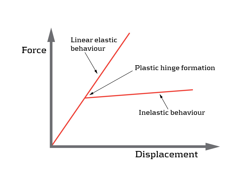
Engineer A carried out the DSA and found the %NBS rating was limited by the shear failure of the coupling beams located in the central service core. Engineer B reviewed Engineer A’s assessment and found that the shear demands in coupling beams were unrealistically high. Engineer B then reviewed the as-built structural information and found that the original design intent back in the late 1980s was to create a weaker coupling beam at each level, so that plastic hinges would develop to dissipate energy and limit the forces in a stable manner. Because Engineer A performed a linear elastic analysis, plastic hinges were not recognized; therefore, the shear force increased with the displacement in a linear manner with no step change to recognize the change of structural behaviour in reality as shown in Figure 2 and Figure 3.

How did Engineer B improve the work?
Engineer B was then engaged by the client to reassess the building. First, Engineer B verified that a nonlinear pushover was appropriate. There are limitations with this type of analysis. For example, because it is static, it cannot capture higher-mode effect that may affect a structure. As a result, Engineer B took the first step to assess the higher-mode effect based on modal mass participation and storey earthquake forces in accordance with the relevant standards and guidelines. He concluded that the subject building was not sensitive to higher-mode effect because of its regularity both in plan and elevation.
Then, he completed a pushover to understand the effect of the design earthquake loading on the structure including both elastic and inelastic (post-yield) behaviours. As a safe practice, he also increased the loading to 1.5 times of the design earthquake and obtained results confirming no collapse mechanisms forming at that level of loading representing the maximum considered earthquake. This was done because earthquakes in reality could exceed those used in design. The final results showed that plastic hinges formed at an early stage mostly at the ends of coupling beams as expected and limited the forces experienced by the building. Figure 4 shows the formation of plastic hinges in the coupled shear wall system.
Figure 4 - Plastic hinge formation in coupled shear wall system of subject building
Conclusion
In conclusion, the seismic rating of the building was revised to 68%NBS (originally 40%NBS). The tenant continued to happily occupy the building.