Earthquake strengthening of unreinforced masonry buildings in New Zealand
Introduction
Unreinforced Masonry (URM) buildings are vulnerable to earthquakes due to their large masses, a lack of integrity between masonry units, and insufficient deformation capacity. The most critical elements are those located at height and unrestrained against lateral loads. Examples of such elements include parapets, chimneys, ornaments and gable end walls. These unrestrained elements can fall during an earthquake and are a significant life-safety risk. The next most critical elements are face-loaded walls which can collapse out of plane and pose a threat to life safety due to a lack of connections to diaphragms and return walls.
Much of our URM building stock in New Zealand is ‘earthquake-prone.’ This means a building is rated at less than 34%NBS (New Building Standard) and it will have its ultimate capacity exceeded even in a moderate earthquake. If it collapses, injury or death is likely. From July 2017, property-owners had to act if their building is considered earthquake-prone. They must carry out earthquake strengthening works on the building so that it is no longer earthquake-prone. We have prepared this article to help building owners better understand their URM building including construction practices, seismic behaviour and earthquake strengthening techniques.
Common Unreinforced Masonry Building Practices in New Zealand
There is a variety of common forms of Unreinforced Masonry (URM) buildings in New Zealand. Many buildings are cellular with internal masonry or timber walls and external URM facades. Commercial buildings typically have an open façade facing the street at the ground floor, and a high ground storey. Other buildings have external perforated walls or punched wall frames and large open plan areas. Church buildings are often more complex and irregular in terms of layout and generally have less internal walls, taller storey heights and more windows; therefore, churches are more vulnerable to earthquakes.
Solid and cavity walls are common types of URM construction. These walls are often supported on concrete strip footings reinforced with plain round bars or other steel elements such as flats and rails. Cavity walls have more than one masonry wythe. The outer wythe is an architectural finish and may be continuous over the full building height. There is usually a single inner wythe at the top storey, and two or three inner wythes at the bottom storey. Common wall thicknesses include 230mm (two wythes), 350mm (three wythes) and 450mm (four wythes) in addition to the outer single-wythe veneer. In cavity wall construction, outer and inner masonry wythes are connected using cavity ties at a typical horizontal spacing of 900mm, and every fifth or sixth course vertically.

Cavity URM wall
There are several different bond patterns found on URM buildings in New Zealand. A bond pattern determines how masonry units in a wall are connected to each other and affects the wall strength and behaviour. A bond pattern is described in terms of stretcher units and header units. Stretcher units are laid in the plane of a wall. Header units are laid across the wall to connect masonry wythes together, so they can act as one complete wall. Common bond patterns in New Zealand include the common bond and English bond. The size of clay bricks in New Zealand is typically 230mm by 110mm by 70mm.

Common brick masonry bond patterns in New Zealand
Many URM buildings in New Zealand have flexible timber floor and roof diaphragms. A timber diaphragm can deform to a greater extent horizontally compared to a concrete slab which is less common in URM buildings in New Zealand. A timber floor diaphragm usually consists of a Tongue and Groove (T&G) membrane supported by timber joists. The connections between the T&G flooring and timber joists are usually nails, which dictate the seismic behaviour of the diaphragm subjected to earthquake loading.
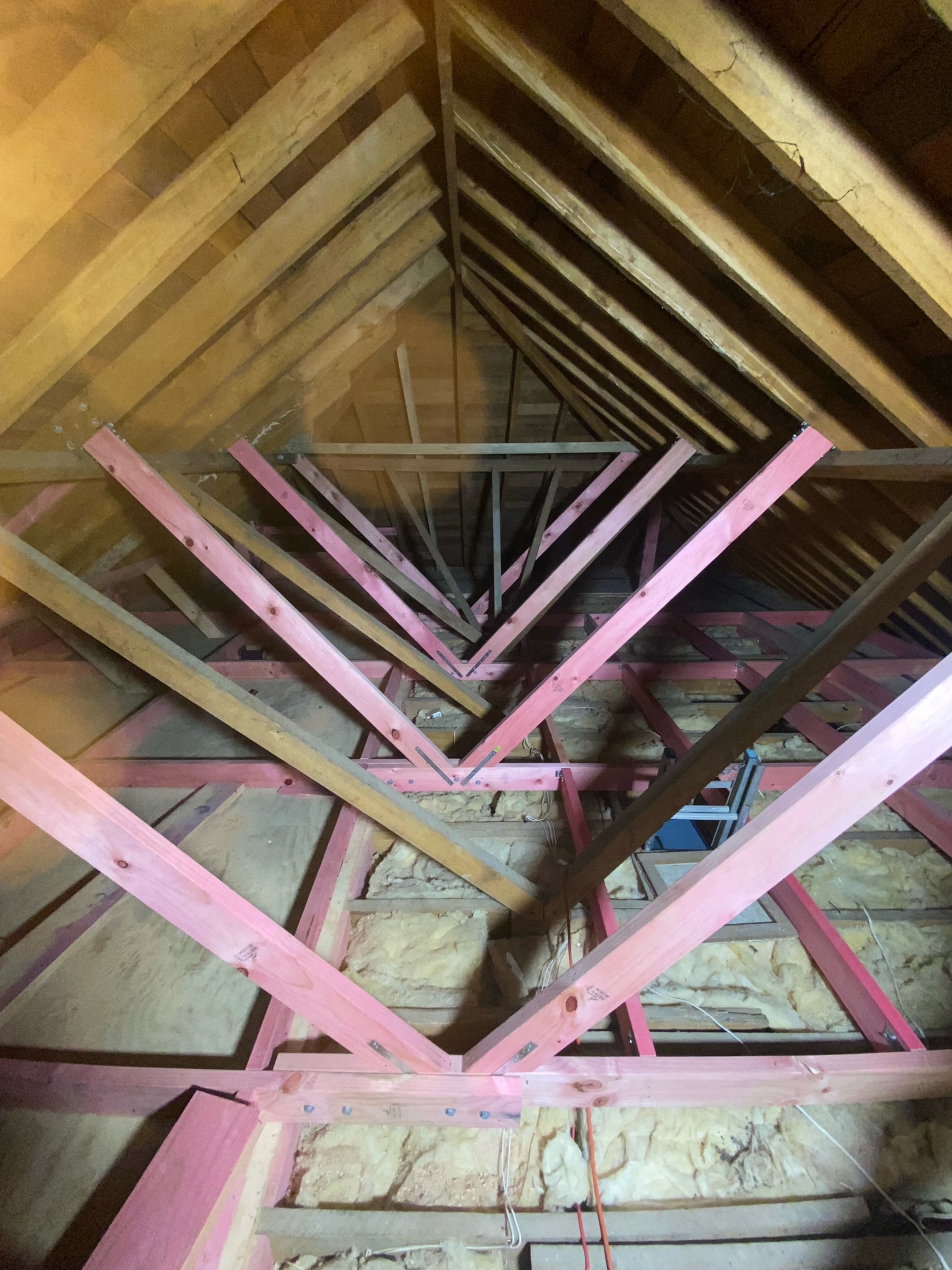
The roof diaphragm is often constructed of timber straight or diagonal sarking boards nailed to timber purlins supported by timber trusses or rafters. Straight sarking boards work in a similar way to T&G flooring boards, but generally have less stiffness and strength. Diagonal sarking boards are stronger and stiffer because they form diagonal struts to purlins and rafters, but have less available ductility compared to straight sarking boards.
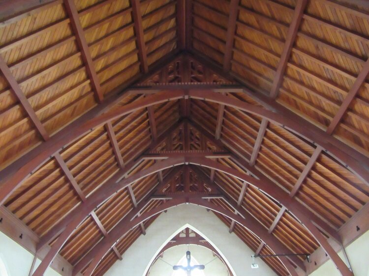
Roof with diagonal sarking
Floor and roof diaphragms are not connected to walls except for a few cases, in which wall-diaphragm anchor plates may be present. At the floor and roof levels, there is often a bond beam built in the external walls. A bond beam is a perimeter tie beam that is reinforced concrete, plain concrete or timber. Bond beams improve the seismic performance of an URM building by distributing diaphragm loads uniformly, tying wythes together in cavity walls, coupling wall panels for in-plane loads and providing out-of-plane support to face-loaded walls.

Example of existing timber floor seating
Seismic Behaviour of Unreinforced Masonry Buildings
The structural weaknesses and failure hierarchy are important to understanding the seismic behaviour of Unreinforced Masonry (URM) buildings. The most critical structural weaknesses are those elements located at height and unrestrained against lateral loads. Examples include parapets, chimneys, ornaments and gable end walls. These unrestrained elements can fall during an earthquake and are a significant life-safety risk. The next most critical elements are face-loaded walls which can collapse out of plane and pose a threat to life safety due to a lack of connections to diaphragms and return walls. When subjected to in-plane loads, walls can fail in a number of different modes as illustrated below.

Brick masonry wall in-plane failure modes
Seismic Improvement of Floor and Roof Diaphragms
In an Unreinforced Masonry (URM) building, structural weaknesses can include insufficient diaphragm strength and stiffness at the roof and floor levels. While there are many retrofit options to earthquake strengthen and stiffen diaphragms, plywood panelling is a popular and cost-effective retrofit system. Because the existing floor was constructed of timber, it is relatively easy to install plywood and new timber framing. If the existing flooring must be retained for aesthetic purposes, a plywood ceiling diaphragm can be built to the underside of the existing floor. When the existing flooring must be retained but appearance is not an issue, plywood overlays can be used. In the absence of any heritage requirements, the existing flooring may be entirely replaced by new plywood sheathing. To effectively transfer shear loads from one panel to another, blocking must be provided at the edges of each panel. It is a smaller timber member nailed to timber joists along plywood edges. It is sometimes difficult to install blocking, especially when the existing flooring is required to remain in place. As an alternative, stapled sheet metal blocking can be used along the plywood edges.

Example of plywood diaphragm
New Wall-Diaphragm Connections
While a diaphragm needs to be strong and stiff enough to transfer loads and support face-loaded walls, there is often a lack of wall-diaphragm connections. To improve the wall-diaphragm connectivity, a section of the existing flooring along walls can be replaced by new plywood and timber blocking connected to the existing timber joists, with new steel anchors installed into the walls. To improve wall-diaphragm connectivity at the roof level, a section of the existing roof cladding can be removed to allow access into the roof space where a new plywood section similar to that used at the floor level can be installed and connected to the walls.

Example of new wall-diaphragm connections
Seismic Restraint of Parapets and Chimneys
Unrestrained parapets and chimneys are common. They are usually cantilevered above the roof structure and can fall out of plane and pose a significant threat to life safety. Parapets can be earthquake strengthened using steel braces, with one end connected to the parapet using epoxy anchors, and the other end to the existing timber roof structure. For earthquake strengthening of chimneys, there are a number of options including post-tensioning, steel hollow sections, concrete filling and steel bracing (inside larger chimneys).

Example of seismic restraint of parapet
Post-Tensioning of Walls
Unreinforced Masonry (URM) walls can be earthquake strengthened using post-tensioning tendons. For both face-loaded and in-plane loaded walls, post-tensioning tendons are used to improve flexural/rocking capacities primarily. Post-tensioning tendons can be installed into cored holes located at the centre of the wall section. Using this method, a hole is first cored from the top of the wall right through to the foundations. A specialist contractor in New Zealand should be able to do this for up to four storeys with a good precision. A tendon is then placed into the cored cavity space. Lastly, a tension load is applied to the tendon. If coring is not possible, the alternative option is to externally install post-tensioning tendons at less visible places such as wall corners. The tendon may be a threaded steel bar or strands. The post-tensioning load is applied using a hydraulic jack at the top of the wall. Prior to the load applied, the other end of the tendon is either bonded to the masonry over a certain bonded length or anchored to the foundations. The hole can be fully grouted after post-tensioning each tendon.

Example of wall post-tensioning
Externally Bonded Fibre-Reinforced Polymer
For earthquake strengthening of Unreinforced Masonry (URM) walls subjected to both in-plane and out-of-plane loads, externally bonded Fibre-Reinforced Polymer (FRP) systems can be used. There are carbon and glass FRP systems. They are formed by the impregnation of high-strength fibres in epoxy resin. There are two forms of FRP: fabrics and plates. A fabric is generally impregnated at site with epoxy to form FRP which is bonded to a wall surface. A plate is produced by pultrusion, which involves pulling of fibres through a resin system into a heated die. FRP plates are bonded to a wall surface using epoxy.
Externally bonded FRP systems include vertical, horizontal, and diagonal strips and plates or a continuous fabric that covers the whole wall surface. They are used primarily to improve the shear strength of a URM wall loaded in plane. For a face-loaded wall, FRP elements are used to improve flexural strength provided that they are installed on both faces of the wall.

Examples of externally bonded FRP strips on walls
Near-Surface Mounted Fibre-Reinforced Polymer
Near-Surface Mounted (NSM) Fibre-Reinforced Polymer (FRP) systems include vertical strips and plates, as well as horizontal strips, strings, and plates. They are intended primarily to improve shear strength of walls loaded in plane. For a face-loaded wall, they are used to improve flexural strength provided that they are installed in both faces of the wall. Horizontal NSM FRP strips, strings and plates are recessed into existing mortar bed joints, which are then repointed. Vertical NSM FRP strips and plates are installed (with epoxy) into very thin pre-cut slots or grooves, which span across several masonry units, with/without anchorages provided at the top and bottom of a wall.

Example of NSM FRP strips and externally bonded wraps
How Can We Help You?
At Tino Seismic, we specialize in providing seismic assessments and strengthening solutions for Unreinforced Masonry (URM) buildings. With our expertise in real earthquake simulations, on-site investigations, and material testing, we are able to provide accurate performance-based assessments and designs that can save you significant time and cost, particularly for larger projects, by avoiding unnecessary strengthening work. We also understand the importance of preserving historic and cultural building heritage, and our approach can help eliminate the impacts of earthquake strengthening on these valuable heritage features. To learn more, please read our case studies or view our range of services, including Initial Seismic Assessment (ISA), Detailed Seismic Assessment (DSA), earthquake strengthening design, building consent, and construction monitoring.